Removable Microclimate Sensor Mounts for Farm Research Sites
To complete microclimate monitoring in an agrivoltaics study, five types of sensors were purchased to measure leaf wetness, ambient temperature and humidity, rainfall, photosynthetically active radiation, and soil moisture and temperature.* The sensors are wireless; they transmit data to a central transponder in the field that is connected to a cellular network. Data is uploaded to the cloud and can be accessed remotely.
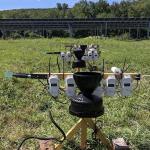
The sensors selected for the study are largely used for permanent weather stations. Our research study required a unique way to deploy these sensors in the fields of study (figure 1). The unit the sensors were mounted on had four requirements:
- Removable from the field with reasonable ease to allow for farm operations.
- Stable and able to maintain a level position, both horizontally and vertically, in adverse weather conditions throughout the season.
- All four above-ground sensors must be mounted at the same height, 24 inches above the soil.**
- Not built of metal due to possible interferences with some of the sensors
The design presented here was tested on eight stands at two locations in 2022. Modifications were made throughout the season based on the prototype field test. At the conclusion of the field season, all stands remained 90-100% level horizontally and vertically. Stands were removed at the end of the growing season to prevent unnecessary exposure to winter conditions and displacement due to frost heaving. A total of 66 stands using this design will be deployed in the 2023 and 2024 growing season.
Tools Required
- Miter saw
- Personal protective equipment
- Power drill and drill bits
- Level
- Tape measure
Basic Construction Outline
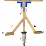
- A = 28” long, 2”x2” untreated pine board.
- B = 27” long, 2”x2” untreated pine board.
- Approximately 5.25” of B is embedded within the ground screw (H) and secured with steel-reinforced epoxy.†
- Although a 2” thick board is used for A, this is an industry dimension and not a true width. The true width is approximately 1.5 inches
- The combination of the embedded board and the added height from A result in a stand height of 23.25”. However, E is flush with the top of F. This 0.75” gap allows space for some soil to build up below the lip of F when the unit is screwed into the ground, which makes installation faster and easier. This also brings the total height to 24”.
- C = 15” long on the longest side of the quadrilateral††, 2”x2” untreated pine board. The edge of C that connects to E is a 40° angle; edge of C that connects to B is a 50° angle.
- D = 13” long on the longest side of the quadrilateral††, 2”x2” untreated pine board. The edge of D that connects to E is a 40° angle; edge of C that connects to B is a 50° angle.
- C and D are intentionally offset to guarantee the screws the connect these pieces to B will not run into each other.
- E = 6”x6”, made from 6”x1” untreated pine board (true thickness is 0.75”).
- F = Ground Screw
- All wood receives two coats of oil-based waterproof wood finish prior to assembly.
Hardware
- One, #2 x 3-1/2” Phillips flat head coarse thread screw connects A to B.
- 5” corner braces reinforce the connection between A and B (difficult to see in this image, note the location of the blue shapes on figure 2 for the placement area) and enable to the unit to withstand moderate torque as it is screwed into the ground using A as a handle. Brackets are installed with #8 x 3/4” wafer head Phillips screws.
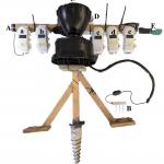
- C and D connect with B with two #8 x 1-3/4” flat head Phillips screws installed at an angle (figure 3).
- A 3/8 in. x 1 in. stainless steel toilet bracket (circled in orange) is connected to B with #8 x 3/4” wafer head Phillips screws.
- The bottom of the bracket sits 10.5” below the top of the stand (top of A). The bracket must be level.
* Sensors purchased from Onset Computer Corporation, Bourne, MA, USA, include RX2106-900 data transmitter, RXW-LIA-900 PAR, RXW-LWA-900 leaf wetness, RXW-RGE-900 rain, RXW-T11-900 soil moisture and temperature, RXW-THC-900 temperature and relative humidity.
** The 24” height was deemed to be appropriate for our experimental design. The stand height can be modified to accommodate experimental goals. If the height is modified, the legs should also be shortened.
† The epoxy means B can never be removed or the ground screws reused. This is an undesirable element of the deign as the ground screws are a substantial expense.
†† The actual lengths vary. The key element is that the legs sit below the toilet bracket and alternate of each other so the screws do not hit each other.
Sensor Installation
Significant modifications were made to install sensors on this unit (figure 3). Effort was made to ensure these modifications followed vendor best practices recommendations and did not impact data collection. Seven of each sensor was monitored in the field in 2022 using this design. Results were compared to regional weather stations using similar sensors from the same vendor, but with traditional installations, to validate results.
- Sensors are installed perpendicular to the ground. This improves light interception and minimizes internal moisture accumulation.
- All sensors motes connected to the stand using the screw included with the sensor. Extra #6 x 3/4“ flat head Phillips screws are beneficial to have.
- The inside of the sensor interior edges of the mote, along the gasket, are lined with dielectric grease to prevent moisture
- It is helpful to have a field code to label all of the sensors, and to maintain a spreadsheet with the codes and the corresponding serial number of the unit. This makes troubleshooting much easier.
- Extra cordage from the sensor to the mote was wrapped up and secured to the stand with cable ties.
- A/a = PAR/mote
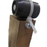
- The sensor is connected to the stand with 8” mounting cable ties. The mounting cable is connected to the stand with a # x 3/4“ wafer head Phillips screw (figure 4).
- The sensor must be level. Two mounting cables improves the fidelity of the leveled position. Only one cable is pictured on figure 3.
- B/b = Soil moisture and temperature/mote
- The sensor is buried according to vendor instructions.
- The cord is covered with 10’ x 3/8” & 1/2“ split flex tubing to prevent animal damage.
- C/c = Rain sensor/mote
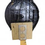
- The rain sensor sits on a 6”x1”x6” self that is secured to the toilet bracket (figure 5). This makes it easier to level the sensor. At the back of the sensor, cable ties secure the sensor to the post.
- D/d= Temperature and humidity/mote
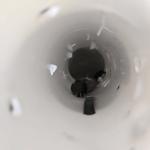
- This sensor requires solar cover. Approximately 8 holes were drilled into a 1 – 1/2 x 6”PVC sink tailpiece to create maximum airflow (figure 6). A cable tie was used to connect the senor to the tailpiece through one additional drilled hole, and a second cable tie was used to connect the tailpiece to the stand through two more additional drilled holes (for a total of 11 holes; 8 for air flow, 3 for installation)..
- E/e = Leaf wetness/mote
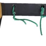
- The mounting bracket purchased from the vendor is secured to the back of unit with #8 x 3/4” wafer head Phillips screws using two pre-drilled holes. With the remaining four drilled holes, wire was used to secure the sensor to the bracket (figure 7).
Close up install details
- Refer to related images 4-7 below.
Pre vs Day Of Mounting Unit Construction
- The feet (E in figure 3) can be screwed into the legs (C and D in figure 3) in advance. However, the legs should not be attached to the center post (B in figure 3) until the unit is screwed into the ground at the research site. If the legs drag along the ground when the unit is screwed in, they may break.
- B should be fixed into E, and then A should be screwed into B once set in advance (including brackets).
- The toilet bracket and shelf can be assembled in advance.
- The leaf wetness sensor bracket can be mounted in advance.
- Cord cover for the soil moisture sensor and wire for the leaf wetness should be cut to size in advance.
- Holes should be drilled in the tailpiece in advance.
- Sensors are best connected with the transmitter and labelled in the office in advance. The dielectric grease should not be applied until the sensors are in the field due to the potential for a mess in the sensor box if overapplied.
Additional Supplies
- A wagon or cart to transport sensors, stands, and install supplies.
- Shims to level stands.
- Extra “feet” to level stands.
- Bricks to place on top of feet to improve stability/levelness as needed.
